Simulateur Arduino Grove
Français · English version below · Exemples du cours
Fait tourner, dans un Arduino virtuel, le programme compilé par PlatformIO : une carte UNO ou
MEGA, son hat Grove, les modules qu'on y branche et le moniteur série. Les cartes et les modules
sont dessinés d'après les vrais, à leurs cotes réelles : on peut comparer sa carte à l'écran. Le
code du projet reste tel quel : le même programme tourne dans le simulateur et sur la vraie carte.
Gratuit, sans compte ni abonnement, et tout se passe dans VS Code. L'interface est en français ou en
anglais, selon la langue de VS Code.
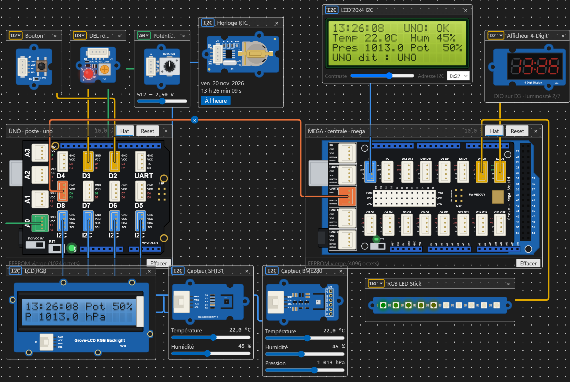
Outil du cours 420-1C4 – Objets connectés (Cégep de Saint-Jérôme). Le mode d'emploi complet est
dans les notes du cours : https://ve2cuy.github.io/4201c4/Documents/Simulateur-Arduino.html.
Ce qu'il faut
- VS Code et l'extension PlatformIO IDE : c'est elle qui compile les programmes.
- Un projet PlatformIO pour un Arduino UNO (
board = uno) ou MEGA (board = megaatmega2560).
Pour commencer
Essayer tout de suite : l'exemple intégré
L'extension contient un exemple complet, à essayer sans rien télécharger ni compiler : un
Arduino MEGA qui affiche la température, l'humidité et la pression (BME280) sur un LCD 20 × 4,
va chercher par Wi-Fi (en HTTPS) les nouvelles du monde de la BBC et les fait défiler, émet un bip
à chaque lecture, anime la barre de DEL et règle le délai entre deux lectures avec un
potentiomètre.
Palette de commandes (Ctrl+Maj+P) : Simulateur Arduino : Ouvrir l'exemple intégré, puis choisir
où créer le projet. Le code est abondamment commenté : c'est un bon point de départ.
Avec votre propre projet
- Ouvrir un projet PlatformIO (un dossier qui contient
platformio.ini).
- Compiler le projet (Ctrl+Alt+B).
- Cliquer sur l'icône du simulateur, en haut à droite de l'éditeur.
- Choisir un module et un port, puis « Ajouter » : le module suit la souris, un clic sur le
canevas fixe sa place (Échap annule).
Après chaque recompilation, la carte redémarre avec le nouveau programme. Le montage est enregistré
dans le fichier circuit.json du projet : on le retrouve à la réouverture.
Les exemples du cours
Chaque exemple s'ouvre d'un clic, montage compris : l'extension le télécharge depuis le site du
cours, demande où créer le projet, puis l'ouvre; la simulation démarre aussitôt, et le code est à
vous pour le modifier et le recompiler.
| Exemple |
Dans les notes |
Ouvrir |
|
| Le premier main.cpp |
Introduction à PlatformIO, section 1.3 |
▶ Ouvrir avec VS Code |
|
| Hello World avec une DEL |
Introduction à PlatformIO, section 5.1 |
▶ Ouvrir avec VS Code |
|
| Hello World avec des macros |
Introduction à PlatformIO, section 5.2 |
▶ Ouvrir avec VS Code |
|
| Un fichier d'en-tête (.h) |
Introduction à PlatformIO, section 6 |
▶ Ouvrir avec VS Code |
|
| Allumer la DEL sur D13 |
Arduino IDE – Hello world, section 1 |
▶ Ouvrir avec VS Code |
|
| Faire clignoter la DEL |
Arduino IDE – Hello world, section 2 |
▶ Ouvrir avec VS Code |
|
| Clignoter la DEL : code documenté |
Arduino IDE – Hello world, section 3 |
▶ Ouvrir avec VS Code |
|
| Clignoter la DEL avec des macros |
Arduino IDE – Hello world, section 4 |
▶ Ouvrir avec VS Code |
|
| Afficher au moniteur série |
Arduino – Serial.println() et digitalRead(), section 1.8 |
▶ Ouvrir avec VS Code |
|
| Streaming.h |
Arduino – Serial.println() et digitalRead(), section 1.10 |
▶ Ouvrir avec VS Code |
|
| La fonction digitalRead() |
Arduino – Serial.println() et digitalRead(), section 2.1 |
▶ Ouvrir avec VS Code |
|
| Bouton et DEL : exemple documenté |
Arduino – Serial.println() et digitalRead(), section 2.6 |
▶ Ouvrir avec VS Code |
|
| L'instruction while |
Arduino – Serial.println() et digitalRead(), section 3.1.1 |
▶ Ouvrir avec VS Code |
|
| Résistance de rappel interne (INPUT_PULLUP) |
Arduino – Serial.println() et digitalRead(), section 4.1 |
▶ Ouvrir avec VS Code |
|
| Permuter une DEL avec un bouton |
Arduino – Serial.println() et digitalRead(), section 5.1 |
▶ Ouvrir avec VS Code |
|
| Anti-rebond d'un bouton |
Arduino – Serial.println() et digitalRead(), section 6 |
▶ Ouvrir avec VS Code |
|
| Lire le potentiomètre |
Arduino – AnalogRead, section 1.1 |
▶ Ouvrir avec VS Code |
|
| Varier l'intensité d'une DEL (PWM) |
Arduino – AnalogRead, section 4.1 |
▶ Ouvrir avec VS Code |
|
| Varier l'intensité d'une DEL : version courte |
Arduino – AnalogRead, section 4.1.2 |
▶ Ouvrir avec VS Code |
|
| La fonction map() : version a |
Arduino – AnalogRead, section 4.4.a |
▶ Ouvrir avec VS Code |
|
| La fonction map() : version b |
Arduino – AnalogRead, section 4.4.b |
▶ Ouvrir avec VS Code |
|
| La fonction map() : version c |
Arduino – AnalogRead, section 4.4.c |
▶ Ouvrir avec VS Code |
|
| Une boucle for |
Arduino – AnalogRead, section 5.1 |
▶ Ouvrir avec VS Code |
|
| Varier l'intensité d'une DEL avec une boucle for |
Arduino – AnalogRead, section 5.2 |
▶ Ouvrir avec VS Code |
|
| Afficher un texte sur le LCD RGB |
Grove – Module LCD-RGB i2c, section 3 |
▶ Ouvrir avec VS Code |
|
| Texte sur fond de couleur |
Grove – Module LCD-RGB i2c, section 3.1 |
▶ Ouvrir avec VS Code |
|
| Projet universel avec #ifdef |
Grove – Module LCD-RGB i2c, section 4.2 |
▶ Ouvrir avec VS Code |
|
| LCD RGB : flux et sprintf |
Grove – Module LCD-RGB i2c, section 4.3 |
▶ Ouvrir avec VS Code |
|
| sprintf et snprintf sur un LCD 20 × 4 |
Grove – Module LCD-RGB i2c, section 4.4.2 |
▶ Ouvrir avec VS Code |
|
| Compilation conditionnelle |
Grove – Module LCD-RGB i2c, section 4.6 |
▶ Ouvrir avec VS Code |
|
| LCD : clear, setCursor et sprintf |
Grove – Module LCD-RGB i2c, section 5.1 |
▶ Ouvrir avec VS Code |
|
| millis() aligné à droite sur le LCD |
Grove – Module LCD-RGB i2c, section 5.2 |
▶ Ouvrir avec VS Code |
|
| Changer la direction de l'affichage |
Grove – Module LCD-RGB i2c, section 5.3 |
▶ Ouvrir avec VS Code |
|
| Déplacer le texte de gauche à droite |
Grove – Module LCD-RGB i2c, section 5.4 |
▶ Ouvrir avec VS Code |
|
| LCD : défilement automatique |
Grove – Module LCD-RGB i2c, section 5.5 |
▶ Ouvrir avec VS Code |
|
| LCD : caractères personnalisés |
Grove – Module LCD-RGB i2c, section 5.6 |
▶ Ouvrir avec VS Code |
|
| Reste de la division (modulo) |
Grove – Module LCD-RGB i2c, section 7.1 |
▶ Ouvrir avec VS Code |
|
| L'opérateur ternaire |
Grove – Module LCD-RGB i2c, section 7.2 |
▶ Ouvrir avec VS Code |
|
| Nombres pairs et impairs |
Grove – Module LCD-RGB i2c, section 7.2.2 |
▶ Ouvrir avec VS Code |
|
| L'instruction switch |
Grove – Module LCD-RGB i2c, section 7.3 |
▶ Ouvrir avec VS Code |
|
| switch : moniteur série et LCD |
Grove – Module LCD-RGB i2c, section 7.3.1 |
▶ Ouvrir avec VS Code |
|
| Laboratoire : menu, bouton et DEL |
Grove – Module LCD-RGB i2c, section 7.3.3 |
▶ Ouvrir avec VS Code |
|
| L'instruction enum |
Grove – Module LCD-RGB i2c, section 7.4 |
▶ Ouvrir avec VS Code |
|
| Affecter une valeur aux éléments d'un enum |
Grove – Module LCD-RGB i2c, section 7.4.1 |
▶ Ouvrir avec VS Code |
|
| Affecter une valeur aux éléments d'un enum (suite) |
Grove – Module LCD-RGB i2c, section 7.4.1 |
▶ Ouvrir avec VS Code |
|
| Gestion d'un menu avec enum |
Grove – Module LCD-RGB i2c, section 7.5 |
▶ Ouvrir avec VS Code |
|
| Utiliser la bibliothèque Streaming |
Utilisation de librairies, section 1.7 |
▶ Ouvrir avec VS Code |
|
| Sa propre bibliothèque locale |
Utilisation de librairies, section 1.8 |
▶ Ouvrir avec VS Code |
|
| L'instruction enum |
L'instruction 'enum' du langage 'C', section 1 |
▶ Ouvrir avec VS Code |
|
| Une variable de type enum |
L'instruction 'enum' du langage 'C', section 2 |
▶ Ouvrir avec VS Code |
|
| Affecter une valeur aux membres d'un enum |
L'instruction 'enum' du langage 'C', section 3 |
▶ Ouvrir avec VS Code |
|
| Un enum : une liste de fruits |
L'instruction 'enum' du langage 'C', section 4 |
▶ Ouvrir avec VS Code |
|
| Gestion d'un menu avec enum |
L'instruction 'enum' du langage 'C', section 5 |
▶ Ouvrir avec VS Code |
|
| Déclarer et utiliser une struct |
Structures et énumération sous C, section 3 |
▶ Ouvrir avec VS Code |
|
| Une structure pour un ennemi |
Structures et énumération sous C, section 5 |
▶ Ouvrir avec VS Code |
|
| Un tableau de structures |
Structures et énumération sous C, section 7 |
▶ Ouvrir avec VS Code |
|
| L'opérateur AND binaire (&) |
Opérations sur les bits, section 1 |
▶ Ouvrir avec VS Code |
|
| L'opérateur OR binaire ( |
) |
Opérations sur les bits, section 2 |
▶ Ouvrir avec VS Code |
| L'opérateur XOR binaire (^) |
Opérations sur les bits, section 3 |
▶ Ouvrir avec VS Code |
|
| L'opérateur NOT binaire (~) |
Opérations sur les bits, section 4 |
▶ Ouvrir avec VS Code |
|
| Les opérateurs de décalage (<< et >>) |
Opérations sur les bits, section 6 |
▶ Ouvrir avec VS Code |
|
| Décalage et opérations sur les bits |
Opérations sur les bits, section 6.1 |
▶ Ouvrir avec VS Code |
|
| Les opérateurs binaires en pratique |
Opérations sur les bits, section 8 |
▶ Ouvrir avec VS Code |
|
| Structures et opérations sur les bits |
Opérations sur les bits, section 9 |
▶ Ouvrir avec VS Code |
|
| Afficher les multiples de 2 sur le 4-Digit |
SHT31 et TM1637, section 2.3.4 |
▶ Ouvrir avec VS Code |
|
| Afficher des chaînes sur le 4-Digit |
SHT31 et TM1637, section 2.4 |
▶ Ouvrir avec VS Code |
|
| Faire sonner le buzzer |
Buzzer et RGB LED Stick, section 1.2 |
▶ Ouvrir avec VS Code |
|
| Allumer une DEL du LED Stick |
Buzzer et RGB LED Stick, section 2.3.1 |
▶ Ouvrir avec VS Code |
|
| Allumer les DEL du LED Stick en séquence |
Buzzer et RGB LED Stick, section 2.3.2 |
▶ Ouvrir avec VS Code |
|
| Régler l'heure, puis la lire |
Grove – RTC_DS1307, section 4.1 |
▶ Ouvrir avec VS Code |
|
| Afficher l'heure : version 1 |
Grove – RTC_DS1307, section 4.2 |
▶ Ouvrir avec VS Code |
|
| Afficher l'heure : version 2 |
Grove – RTC_DS1307, section 4.3 |
▶ Ouvrir avec VS Code |
|
| Afficher l'heure : version optimisée |
Grove – RTC_DS1307, section 4.4 |
▶ Ouvrir avec VS Code |
|
| Détecteur de mouvement et DEL |
Détecteur de mouvements, section 2 |
▶ Ouvrir avec VS Code |
|
| Clignoter une DEL avec millis() |
Opérations non bloquantes, section 1 |
▶ Ouvrir avec VS Code |
|
| Une interruption matérielle |
Opérations non bloquantes, section 4 |
▶ Ouvrir avec VS Code |
|
| Interruption Timer pour clignoter une DEL |
Opérations non bloquantes, section 5 |
▶ Ouvrir avec VS Code |
|
| Trace d'un programme avec un Timer |
Opérations non bloquantes, section 5.1 |
▶ Ouvrir avec VS Code |
|
| Deux Arduino par UART : SoftwareSerial |
Écoute-moi, j'aimerais te parler, sections 2b.1 et 2b.2 |
▶ Ouvrir avec VS Code |
|
| Des messages du UNO vers le MEGA |
Écoute-moi, j'aimerais te parler, sections 3.1 et 3.2 |
▶ Ouvrir avec VS Code |
|
| UNO sur SoftwareSerial, MEGA sur UART2 |
Écoute-moi, j'aimerais te parler, sections 3.5.1 et 3.5.2 |
▶ Ouvrir avec VS Code |
|
| Un système d'alarme à deux Arduino |
Écoute-moi, j'aimerais te parler, sections 4.2 et 4.3 |
▶ Ouvrir avec VS Code |
|
| Les commandes AT du module Wi-Fi |
Grove – UART Wifi V2, section 4.1 |
▶ Ouvrir avec VS Code |
|
| WiFiEsp : afficher les réseaux disponibles |
Grove – UART Wifi V2, section 4.2 |
▶ Ouvrir avec VS Code |
|
| Requête vers une API Web |
Grove – UART Wifi V2, section 5.1 |
▶ Ouvrir avec VS Code |
|
| Lire les codes d'une télécommande |
Infrarouge : récepteur et émetteur, section 4 |
▶ Ouvrir avec VS Code |
|
| Contrôler une DEL avec une télécommande |
Infrarouge : récepteur et émetteur, section 5 |
▶ Ouvrir avec VS Code |
|
| Compteur de démarrages dans l'EEPROM |
La mémoire EEPROM, section 4 |
▶ Ouvrir avec VS Code |
|
| EEPROM.update() : retenir l'intensité de la DEL |
La mémoire EEPROM, section 5 |
▶ Ouvrir avec VS Code |
|
| EEPROM.put() et EEPROM.get() : une configuration |
La mémoire EEPROM, section 6 |
▶ Ouvrir avec VS Code |
|
| Afficher le contenu de l'EEPROM |
La mémoire EEPROM, section 7.1 |
▶ Ouvrir avec VS Code |
|
| Effacer l'EEPROM |
La mémoire EEPROM, section 7.2 |
▶ Ouvrir avec VS Code |
|
| Lire une carte RFID |
Capteur RFID de Grove, section 1 |
▶ Ouvrir avec VS Code |
|
| Séquences ANSI au moniteur série |
Copier/Coller et projets Wokwi, section A.5 |
▶ Ouvrir avec VS Code |
|
| Bouton, compteur et relais |
Copier/Coller et projets Wokwi, section 7.1 |
▶ Ouvrir avec VS Code |
|
| La mémoire : char[] ou String |
Copier/Coller et projets Wokwi, section 8 |
▶ Ouvrir avec VS Code |
|
| LCD RGB : variation du rouge |
Copier/Coller et projets Wokwi, section 12 |
▶ Ouvrir avec VS Code |
|
| LCD RGB : défilement de caractères |
Copier/Coller et projets Wokwi, section 13 |
▶ Ouvrir avec VS Code |
|
| millis() en jours, heures, minutes et secondes |
Copier/Coller et projets Wokwi, section 16 |
▶ Ouvrir avec VS Code |
|
| Transmettre par UART ou par des broches numériques |
Copier/Coller et projets Wokwi, section 18 |
▶ Ouvrir avec VS Code |
|
Projet complet : la station Grove, deux Arduino
reliés par UART et les 17 modules, chacun activable au menu (télécharger l'archive).
Ce qui est émulé
- Cartes : Arduino UNO R3 (ATmega328P, hat Base Shield V2) et Arduino MEGA 2560 (ATmega2560,
hat Grove Mega Shield), à partir du vrai firmware compilé.
- Modules Grove : DEL (rouge, verte, bleue), bouton, détecteur de mouvement, relais, buzzer,
potentiomètre, afficheur 4-Digit (TM1637), RGB LED Stick, LCD RGB, LCD 20 × 4 I2C, capteurs
SHT31, BME280 et BMP280, horloge RTC DS1307, module Wi-Fi (ESP8266, commandes AT, HTTP et HTTPS), lecteur RFID
125 kHz, récepteur infrarouge avec sa télécommande (protocole NEC).
- Aussi : le moniteur série, l'EEPROM (conservée d'une séance à l'autre), et plusieurs cartes
reliées par un câble UART.
- Oscilloscope : quatre voies sur les broches, les lignes série et le bus I2C, avec décodage
UART, I2C et PWM.
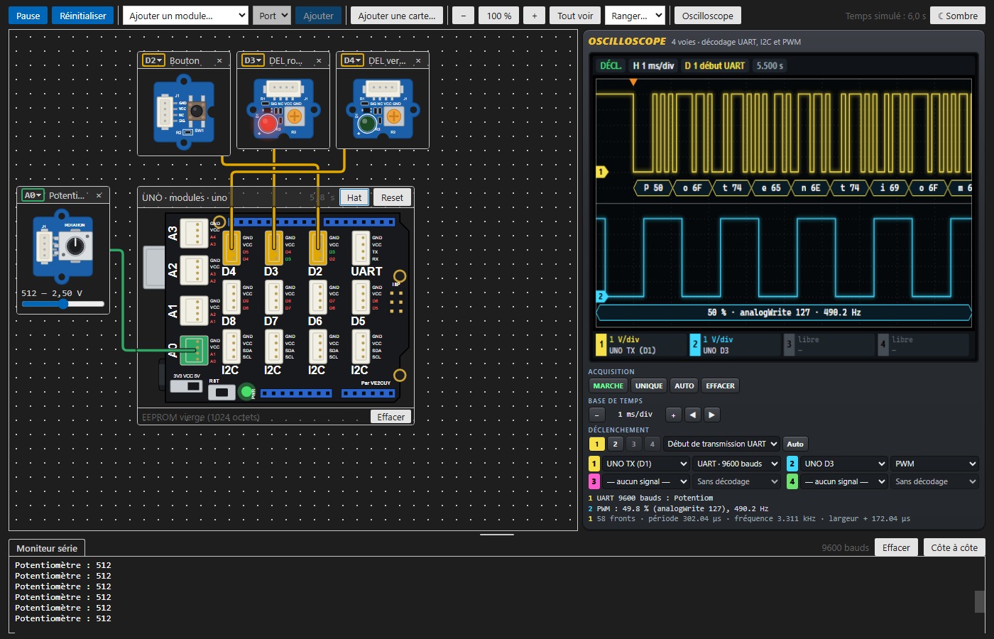
Avec ou sans le hat
Le bouton « Hat » de l'en-tête d'une carte pose ou retire son hat Grove. Sans le hat, on voit la
carte seule : ses pistes s'illuminent quand un signal y passe, et les modules s'y branchent par
des fils. La DEL et le bouton deviennent alors des composants nus, avec leur résistance.
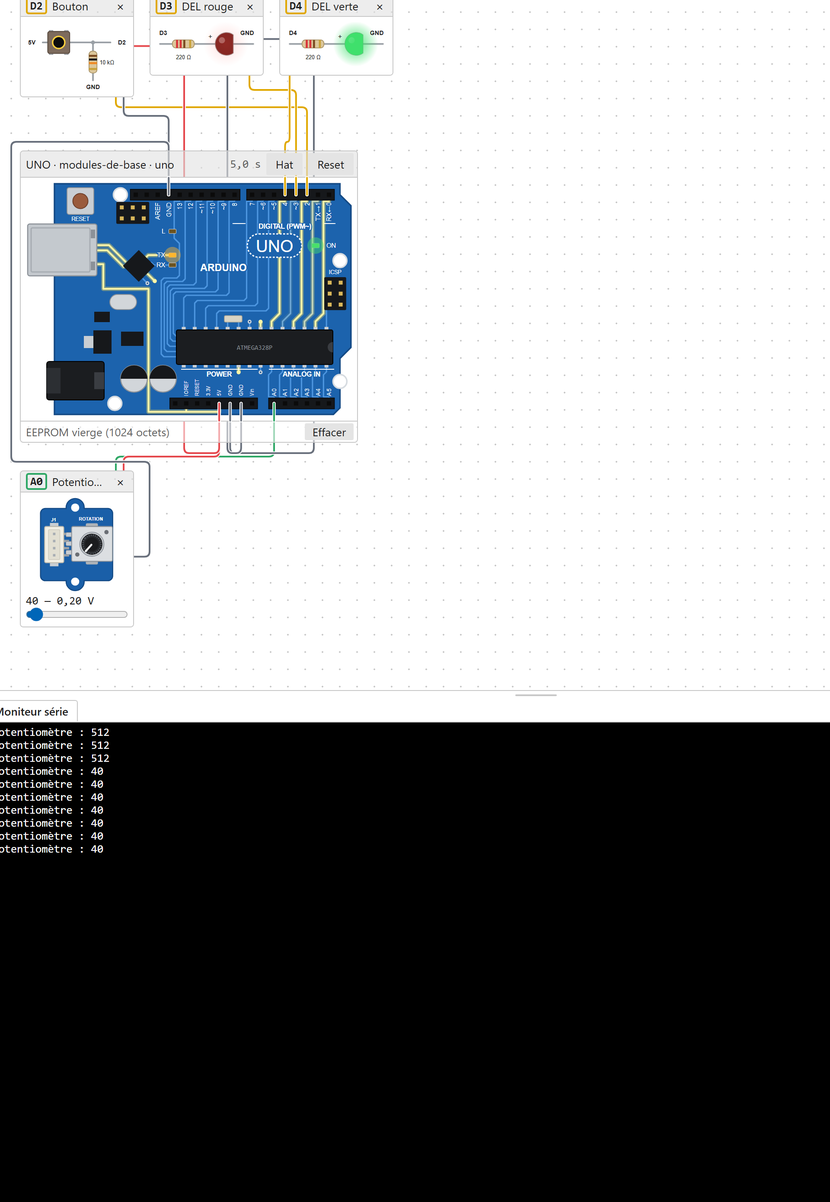
Sur le hat, les noms des broches passent au vert quand la broche est à 1, au rouge quand elle
est à 0. Sur les liens série, les octets circulent en 0 et 1 le long du câble, avec une flèche
qui montre leur sens.
Le bouton « 🔇 Son » du buzzer le fait sonner dans les haut-parleurs de l'ordinateur, à la
fréquence de tone() (coupé par défaut).
L'option « Rebonds » sous un bouton fait rebondir son contact (1 à 5 ms) à l'appui et au
relâchement, comme un vrai bouton : à l'oscilloscope, on voit la rafale de fronts d'un seul appui,
et pourquoi un programme a besoin d'un anti-rebond.
Sur le canevas
- Un clic sur un module met en surbrillance son câble et la prise où il est branché.
- Le port, dans l'en-tête du module, se change dans sa liste : le module garde sa place.
- Suppr retire le module sélectionné.
- Ctrl+Z annule les dernières actions : retrait d'un module, d'un câble ou d'une carte,
déplacement d'un élément ou d'une carte avec ses modules, « Ranger… ».
- La molette agrandit ou réduit le montage; « Tout voir » le montre en entier.
Deux cartes reliées par UART
Mettre les deux projets dans un même espace de travail, ouvrir le simulateur sur l'un, cliquer sur
« Ajouter une carte… » et choisir l'autre, puis poser le câble avec « Relier deux cartes… ». Le
montage est enregistré dans montage.json, à côté du fichier .code-workspace.
Commandes et réglages
Dans la palette de commandes (Ctrl+Maj+P), sous « Simulateur Arduino » : Afficher le
simulateur, Démarrer la simulation, Compiler et simuler.
| Réglage |
Rôle |
simulateurGrove.ouvrirAuDemarrage |
Ouvrir le simulateur dès l'ouverture du dossier ou de l'espace de travail |
simulateurGrove.api.image, simulateurGrove.api.port |
L'onglet « API » du projet de session du cours (conteneur Docker) |
Bon à savoir
- Le module Wi-Fi ouvre de vraies connexions Internet, depuis l'ordinateur, vers les
adresses que le programme demande. Il accepte n'importe quel nom de réseau et mot de passe.
- Le simulateur ne fait que des signaux logiques : l'oscilloscope ne trace pas une tension
analogique, et l'émetteur infrarouge n'est pas simulé (le récepteur, oui).
- Sur un ordinateur lent, le temps simulé peut avancer moins vite que le temps réel.
Licence
Extension sous licence MIT, par Alain Boudreault (VE2CUY). Elle inclut avr8js et xterm.js, eux
aussi sous licence MIT (voir THIRD-PARTY-NOTICES.md dans le paquet).
Arduino Grove Simulator (English)
Runs the program compiled by PlatformIO on a virtual Arduino: an UNO or MEGA board, its Grove
hat, the modules plugged into it, and the serial monitor. Boards and modules are drawn from the
real ones, at their actual size, so students can compare their own board with the screen. The
project code stays as is: the same program runs in the simulator and on the real board.
Free, no account or subscription needed, and everything happens inside VS Code. The interface is
in English or French, following the language of VS Code.
Made for the course 420-1C4 – Objets connectés (Cégep de Saint-Jérôme, Québec). The full manual,
in French, is in the course notes: https://ve2cuy.github.io/4201c4/Documents/Simulateur-Arduino.html.
Requirements
- VS Code and the PlatformIO IDE extension, which compiles the programs.
- A PlatformIO project for an Arduino UNO (
board = uno) or MEGA (board = megaatmega2560).
Getting started
Try it right away: the built-in example
The extension ships with a complete example, to try without downloading or building anything: an
Arduino MEGA that shows the temperature, humidity and pressure (BME280) on a 20 × 4 LCD, fetches
the BBC world news over Wi-Fi (HTTPS) and scrolls them, beeps at each read, animates the
LED bar and sets the delay between two reads with a potentiometer.
Command Palette (Ctrl+Shift+P): Arduino Simulator: Open the built-in example, then choose where
to create the project. The code is thoroughly commented (in French): a good starting point.
With your own project
- Open a PlatformIO project (a folder containing
platformio.ini).
- Build the project (Ctrl+Alt+B).
- Click the simulator icon at the top right of the editor.
- Pick a module and a port, then Add: the module follows the mouse, and a click on the canvas
sets its place (Esc cancels).
After each build, the board restarts with the new program. The setup is saved in the project's
circuit.json file and comes back when the project is reopened.
Course examples
Each example opens in one click, setup included: the extension downloads it from the course
website, asks where to create the project, then opens it; the simulation starts right away, and the
code is yours to modify and rebuild. The examples and their notes are in French.
| Example |
In the notes |
Open |
|
| The first main.cpp |
Introduction à PlatformIO, section 1.3 |
▶ Open with VS Code |
|
| Hello World with an LED |
Introduction à PlatformIO, section 5.1 |
▶ Open with VS Code |
|
| Hello World with macros |
Introduction à PlatformIO, section 5.2 |
▶ Open with VS Code |
|
| A header file (.h) |
Introduction à PlatformIO, section 6 |
▶ Open with VS Code |
|
| Turn on the LED on D13 |
Arduino IDE – Hello world, section 1 |
▶ Open with VS Code |
|
| Blink the LED |
Arduino IDE – Hello world, section 2 |
▶ Open with VS Code |
|
| Blink the LED: documented code |
Arduino IDE – Hello world, section 3 |
▶ Open with VS Code |
|
| Blink the LED with macros |
Arduino IDE – Hello world, section 4 |
▶ Open with VS Code |
|
| Print to the serial monitor |
Arduino – Serial.println() et digitalRead(), section 1.8 |
▶ Open with VS Code |
|
| Streaming.h |
Arduino – Serial.println() et digitalRead(), section 1.10 |
▶ Open with VS Code |
|
| The digitalRead() function |
Arduino – Serial.println() et digitalRead(), section 2.1 |
▶ Open with VS Code |
|
| Button and LED: documented example |
Arduino – Serial.println() et digitalRead(), section 2.6 |
▶ Open with VS Code |
|
| The while statement |
Arduino – Serial.println() et digitalRead(), section 3.1.1 |
▶ Open with VS Code |
|
| Internal pull-up resistor (INPUT_PULLUP) |
Arduino – Serial.println() et digitalRead(), section 4.1 |
▶ Open with VS Code |
|
| Toggle an LED with a button |
Arduino – Serial.println() et digitalRead(), section 5.1 |
▶ Open with VS Code |
|
| Button debouncing |
Arduino – Serial.println() et digitalRead(), section 6 |
▶ Open with VS Code |
|
| Read the potentiometer |
Arduino – AnalogRead, section 1.1 |
▶ Open with VS Code |
|
| Fade an LED (PWM) |
Arduino – AnalogRead, section 4.1 |
▶ Open with VS Code |
|
| Fade an LED: short version |
Arduino – AnalogRead, section 4.1.2 |
▶ Open with VS Code |
|
| The map() function: version a |
Arduino – AnalogRead, section 4.4.a |
▶ Open with VS Code |
|
| The map() function: version b |
Arduino – AnalogRead, section 4.4.b |
▶ Open with VS Code |
|
| The map() function: version c |
Arduino – AnalogRead, section 4.4.c |
▶ Open with VS Code |
|
| A for loop |
Arduino – AnalogRead, section 5.1 |
▶ Open with VS Code |
|
| Fade an LED with a for loop |
Arduino – AnalogRead, section 5.2 |
▶ Open with VS Code |
|
| Show text on the RGB LCD |
Grove – Module LCD-RGB i2c, section 3 |
▶ Open with VS Code |
|
| Text on a colored background |
Grove – Module LCD-RGB i2c, section 3.1 |
▶ Open with VS Code |
|
| Universal project with #ifdef |
Grove – Module LCD-RGB i2c, section 4.2 |
▶ Open with VS Code |
|
| RGB LCD: streams and sprintf |
Grove – Module LCD-RGB i2c, section 4.3 |
▶ Open with VS Code |
|
| sprintf and snprintf on a 20 × 4 LCD |
Grove – Module LCD-RGB i2c, section 4.4.2 |
▶ Open with VS Code |
|
| Conditional compilation |
Grove – Module LCD-RGB i2c, section 4.6 |
▶ Open with VS Code |
|
| LCD: clear, setCursor and sprintf |
Grove – Module LCD-RGB i2c, section 5.1 |
▶ Open with VS Code |
|
| millis() right-aligned on the LCD |
Grove – Module LCD-RGB i2c, section 5.2 |
▶ Open with VS Code |
|
| Change the text direction |
Grove – Module LCD-RGB i2c, section 5.3 |
▶ Open with VS Code |
|
| Move the text left and right |
Grove – Module LCD-RGB i2c, section 5.4 |
▶ Open with VS Code |
|
| LCD: autoscroll |
Grove – Module LCD-RGB i2c, section 5.5 |
▶ Open with VS Code |
|
| LCD: custom characters |
Grove – Module LCD-RGB i2c, section 5.6 |
▶ Open with VS Code |
|
| Remainder of a division (modulo) |
Grove – Module LCD-RGB i2c, section 7.1 |
▶ Open with VS Code |
|
| The ternary operator |
Grove – Module LCD-RGB i2c, section 7.2 |
▶ Open with VS Code |
|
| Even and odd numbers |
Grove – Module LCD-RGB i2c, section 7.2.2 |
▶ Open with VS Code |
|
| The switch statement |
Grove – Module LCD-RGB i2c, section 7.3 |
▶ Open with VS Code |
|
| switch: serial monitor and LCD |
Grove – Module LCD-RGB i2c, section 7.3.1 |
▶ Open with VS Code |
|
| Lab: menu, button and LED |
Grove – Module LCD-RGB i2c, section 7.3.3 |
▶ Open with VS Code |
|
| The enum statement |
Grove – Module LCD-RGB i2c, section 7.4 |
▶ Open with VS Code |
|
| Assign values to enum elements |
Grove – Module LCD-RGB i2c, section 7.4.1 |
▶ Open with VS Code |
|
| Assign values to enum elements (continued) |
Grove – Module LCD-RGB i2c, section 7.4.1 |
▶ Open with VS Code |
|
| A menu driven by an enum |
Grove – Module LCD-RGB i2c, section 7.5 |
▶ Open with VS Code |
|
| Using the Streaming library |
Utilisation de librairies, section 1.7 |
▶ Open with VS Code |
|
| Your own local library |
Utilisation de librairies, section 1.8 |
▶ Open with VS Code |
|
| The enum statement |
L'instruction 'enum' du langage 'C', section 1 |
▶ Open with VS Code |
|
| An enum-typed variable |
L'instruction 'enum' du langage 'C', section 2 |
▶ Open with VS Code |
|
| Assign values to enum members |
L'instruction 'enum' du langage 'C', section 3 |
▶ Open with VS Code |
|
| An enum: a list of fruits |
L'instruction 'enum' du langage 'C', section 4 |
▶ Open with VS Code |
|
| A menu driven by an enum |
L'instruction 'enum' du langage 'C', section 5 |
▶ Open with VS Code |
|
| Declare and use a struct |
Structures et énumération sous C, section 3 |
▶ Open with VS Code |
|
| A structure for an enemy |
Structures et énumération sous C, section 5 |
▶ Open with VS Code |
|
| An array of structures |
Structures et énumération sous C, section 7 |
▶ Open with VS Code |
|
| The bitwise AND operator (&) |
Opérations sur les bits, section 1 |
▶ Open with VS Code |
|
| The bitwise OR operator ( |
) |
Opérations sur les bits, section 2 |
▶ Open with VS Code |
| The bitwise XOR operator (^) |
Opérations sur les bits, section 3 |
▶ Open with VS Code |
|
| The bitwise NOT operator (~) |
Opérations sur les bits, section 4 |
▶ Open with VS Code |
|
| The shift operators (<< and >>) |
Opérations sur les bits, section 6 |
▶ Open with VS Code |
|
| Shifts and bit operations |
Opérations sur les bits, section 6.1 |
▶ Open with VS Code |
|
| Bitwise operators in practice |
Opérations sur les bits, section 8 |
▶ Open with VS Code |
|
| Structures and bit operations |
Opérations sur les bits, section 9 |
▶ Open with VS Code |
|
| Show multiples of 2 on the 4-Digit display |
SHT31 et TM1637, section 2.3.4 |
▶ Open with VS Code |
|
| Show strings on the 4-Digit display |
SHT31 et TM1637, section 2.4 |
▶ Open with VS Code |
|
| Sound the buzzer |
Buzzer et RGB LED Stick, section 1.2 |
▶ Open with VS Code |
|
| Light one LED of the LED Stick |
Buzzer et RGB LED Stick, section 2.3.1 |
▶ Open with VS Code |
|
| Light the LED Stick in sequence |
Buzzer et RGB LED Stick, section 2.3.2 |
▶ Open with VS Code |
|
| Set the time, then read it |
Grove – RTC_DS1307, section 4.1 |
▶ Open with VS Code |
|
| Show the time: version 1 |
Grove – RTC_DS1307, section 4.2 |
▶ Open with VS Code |
|
| Show the time: version 2 |
Grove – RTC_DS1307, section 4.3 |
▶ Open with VS Code |
|
| Show the time: optimized version |
Grove – RTC_DS1307, section 4.4 |
▶ Open with VS Code |
|
| Motion detector and LED |
Détecteur de mouvements, section 2 |
▶ Open with VS Code |
|
| Blink an LED with millis() |
Opérations non bloquantes, section 1 |
▶ Open with VS Code |
|
| A hardware interrupt |
Opérations non bloquantes, section 4 |
▶ Open with VS Code |
|
| Timer interrupt to blink an LED |
Opérations non bloquantes, section 5 |
▶ Open with VS Code |
|
| Tracing a program with a timer |
Opérations non bloquantes, section 5.1 |
▶ Open with VS Code |
|
| Two Arduinos over UART: SoftwareSerial |
Écoute-moi, j'aimerais te parler, sections 2b.1 et 2b.2 |
▶ Open with VS Code |
|
| Messages from the UNO to the MEGA |
Écoute-moi, j'aimerais te parler, sections 3.1 et 3.2 |
▶ Open with VS Code |
|
| UNO on SoftwareSerial, MEGA on UART2 |
Écoute-moi, j'aimerais te parler, sections 3.5.1 et 3.5.2 |
▶ Open with VS Code |
|
| An alarm system with two Arduinos |
Écoute-moi, j'aimerais te parler, sections 4.2 et 4.3 |
▶ Open with VS Code |
|
| AT commands of the Wi-Fi module |
Grove – UART Wifi V2, section 4.1 |
▶ Open with VS Code |
|
| WiFiEsp: list the available networks |
Grove – UART Wifi V2, section 4.2 |
▶ Open with VS Code |
|
| Request to a web API |
Grove – UART Wifi V2, section 5.1 |
▶ Open with VS Code |
|
| Read the codes of a remote control |
Infrarouge : récepteur et émetteur, section 4 |
▶ Open with VS Code |
|
| Control an LED with a remote control |
Infrarouge : récepteur et émetteur, section 5 |
▶ Open with VS Code |
|
| Boot counter in EEPROM |
La mémoire EEPROM, section 4 |
▶ Open with VS Code |
|
| EEPROM.update(): remember the LED brightness |
La mémoire EEPROM, section 5 |
▶ Open with VS Code |
|
| EEPROM.put() and EEPROM.get(): a configuration |
La mémoire EEPROM, section 6 |
▶ Open with VS Code |
|
| Dump the EEPROM contents |
La mémoire EEPROM, section 7.1 |
▶ Open with VS Code |
|
| Erase the EEPROM |
La mémoire EEPROM, section 7.2 |
▶ Open with VS Code |
|
| Read an RFID card |
Capteur RFID de Grove, section 1 |
▶ Open with VS Code |
|
| ANSI sequences in the serial monitor |
Copier/Coller et projets Wokwi, section A.5 |
▶ Open with VS Code |
|
| Button, counter and relay |
Copier/Coller et projets Wokwi, section 7.1 |
▶ Open with VS Code |
|
| Memory: char[] or String |
Copier/Coller et projets Wokwi, section 8 |
▶ Open with VS Code |
|
| RGB LCD: red fade |
Copier/Coller et projets Wokwi, section 12 |
▶ Open with VS Code |
|
| RGB LCD: scrolling characters |
Copier/Coller et projets Wokwi, section 13 |
▶ Open with VS Code |
|
| millis() as days, hours, minutes and seconds |
Copier/Coller et projets Wokwi, section 16 |
▶ Open with VS Code |
|
| Transmit over UART or digital pins |
Copier/Coller et projets Wokwi, section 18 |
▶ Open with VS Code |
|
Complete project: the Grove station, two Arduino
boards linked by UART and all 17 modules, each one enabled from a menu (download the archive).
What is emulated
- Boards: Arduino UNO R3 (ATmega328P, Base Shield V2 hat) and Arduino MEGA 2560 (ATmega2560,
Grove Mega Shield hat), running the real compiled firmware.
- Grove modules: LEDs (red, green, blue), button, motion sensor, relay, buzzer,
potentiometer, 4-Digit display (TM1637), RGB LED Stick, RGB LCD, 20 × 4 I2C LCD, SHT31, BME280
and BMP280 sensors, DS1307 real-time clock, Wi-Fi module (ESP8266, AT commands, HTTP and HTTPS), 125 kHz RFID
reader, infrared receiver with its remote control (NEC protocol).
- Also: the serial monitor, the EEPROM (kept from one session to the next), and several boards
linked by a UART cable.
- Oscilloscope: four channels on the pins, the serial lines and the I2C bus, with UART, I2C
and PWM decoding.
With or without the hat
The Hat button in a board's header puts its Grove hat on or takes it off. Without the hat, the
bare board shows: its traces light up when a signal goes through, and the modules are connected
to its pins by wires. The LED and the button then become bare components, with their resistor.
On the hat, pin names turn green when the pin is at 1 and red when it is at 0. On serial links,
the bytes travel along the cable as 0s and 1s, with an arrow showing their direction.
The buzzer's 🔇 Sound button makes it sound through the computer's speakers, at the frequency
given to tone() (muted by default).
The Bounce option under a button makes its contact bounce (1 to 5 ms) when pressed and
released, like a real button: the oscilloscope shows the burst of edges from a single press, and why
a program needs debouncing.
On the canvas
- Clicking a module highlights its cable and the socket it is plugged into.
- The port, in the module's header, can be changed from its list: the module keeps its place.
- Delete removes the selected module.
- Ctrl+Z undoes the latest actions: removing a module, a cable or a board, moving an element or a
board with its modules, Arrange….
- The mouse wheel zooms the setup in and out; Show all fits it on screen.
Two boards linked by UART
Put both projects in the same workspace, open the simulator on one of them, click Add a board…
and pick the other one, then lay the cable with Link two boards…. The setup is saved in
montage.json, next to the .code-workspace file.
Commands and settings
In the command palette (Ctrl+Shift+P), under « Arduino Simulator »: Show the simulator,
Start the simulation, Build and simulate.
| Setting |
Purpose |
simulateurGrove.ouvrirAuDemarrage |
Open the simulator as soon as the folder or workspace is opened |
simulateurGrove.api.image, simulateurGrove.api.port |
The API tab of the course's term project (Docker container) |
Good to know
- The Wi-Fi module opens real Internet connections, from the computer, to the addresses
the program asks for. It accepts any network name and password.
- The simulator only handles logic signals: the oscilloscope does not plot an analog voltage,
and the infrared emitter is not simulated (the receiver is).
- On a slow computer, simulated time may run slower than real time.
- The screenshots on this page show the French interface.
License
MIT-licensed extension, by Alain Boudreault (VE2CUY). It includes avr8js and xterm.js, also under
the MIT license (see THIRD-PARTY-NOTICES.md in the package).
| |